Thanks, I did install Europe and found v2 included.
Tutorial for Creating ABattleMap Modules v1.0
-
Hey Stoney! Good job on the modules! I haven’t looked but have you updated or added to the tutorial for making modules? Feel free to add the next chapter to the knowledge base for everyone to find and use etc. Thanks!
@P@nther:
One far day I will have learned the secrets of ABattlemap ;-)
That day is here! Over the past couple months I have been working on writing a tutorial for creating an ABattleMap module.
If you’ve got a slow connection and you’d like something a little faster, you can download a .pdf copy here: http://www.mediafire.com/file/jzj1fjddn5m/Tutorial 1_0.pdf
or if you’d like to add to it yourself, you can download an editable .rtf here: http://www.mediafire.com/file/w0y43klizji/Tutorial 1_0 rtf.zipEnjoy!
Stoney229’s tutorial for creating ABattleMap modules
Version 1.01Information about this tutorial
This tutorial is based on the latest version of ABattleMap as of June 16, 2010, which is only found packaged with Attila’s Pacific 1940 module, here: http://www.flames-of-europe.de/modules.php?name=Downloads&d_op=getit&lid=107, and is referred to as “0.80+” in this tutorial. Information and instructions related to image-editing are based on the latest version (v3.5.5) of the image-editing program Paint.NETC, which can be downloaded here: http://www.getpaint.net/ . Operating System related instructions are based on recent Windows desktop operating systems.
The content of this tutorial is based in part on tutorials by Attila, TMTM, and HolKann. Credit goes to them for beginning the work and making this easier for me. It has been designed more as a sort of manual, rather than a step-by-step tutorial, with the intent of offering a better understanding of how things work. Do not be intimidated by its length: any software that takes 2 minutes to figure out still comes with a 30-page help file! While it can be used as a step-by-step guide, you may find it more enjoyable to explore things on your own before reading the tutorial in detail - consulting this tutorial only when you would like some guidance. Feel free to reproduce and/or modify this tutorial (with or without citation or credit to me) as you see fit.
Superscripts refer to dedicated sections which offer more comprehensive and detailed explanations.
Use Ctrl+F to search for a specific topic.
If you have any questions, suggestions, corrections, etc., please post them on this thread. Even pointing out typos or grammatical errors would be appreciated. Thanks!
-
Contents
Section A: The files that make up a module
Section B: Steps for creating a module
Section C: The image-editing program- Paint.NET
Section D: Map.bmp
Section E: SektorInfo.bmp
Section F: SektorInfo.map
Section G: ToolPieces.bmp
Section H: BigPieces.bmp
Section I: UnitStats.txt
Section J: ToolPieces.txt
Section K: MapInfo.txt
Section L: SektorInfo.sek
Section M: Using Sektor Editor
Section N: SektorInfo.txt
Section O: Start.aam
Section P: Using ABattleMap’s file conversion tools
Section Q: The hexadecimal number system
Section R: .zip files
Section S: Uploading for internet distribution
Section T: Glossary
Section U: The FAQ
Section V: Change log -
Section A: The files that make up a module
The “.gim” folder*
All of the files which make up a module are contained in a single folder. This folder can have any name of 1-3 characters in length, ending in the suffix “.gim”. No two .GIM folders can have the same name. All .GIM folders must be placed directly in the ABattleMap program folder, which is usually located at C:\Program Files\ABattleMap. .GIM folders may contain any files or folders, even if they are not used by the module. However, files must be directly in the .GIM folder (not in a subfolder) in order to be used by the module.The following is an alphabetical list of files used to create a module. Not all of these files are required for a module to function:
BigPieces.bmpH
This is the image file displayed in ABattleMap’s “ToolBar” window when a user has the “Use BigPieces” option selected in ABattleMap’s “View” menu.Map.bmpD*
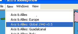
This is the image file displayed in ABattleMap’s main window when a user selects the module in ABattleMap’s “New” menu. It normally represents the game board, but sometimes includes other areas as well (e.g. reference panels or charts, toolbars for keeping track of cash and technology, etc.).MapInfo.txtK*
This text file contains the name of the module as it appears in ABattleMap’s “View” menu. It also includes the information of which powers are aligned together on a team.SektorInfo.bmpE
This image file is used to create SektorInfo.mapF.SektorInfo.mapF
This file contains the information of which sector (territory, sea zone, space, etc.) each pixel on the map belongs to.SektorInfo.sekL
This file contains all the information (except map/board location) about specific sectors, including name (as displayed in ABattleMap’s title bar), type (land or water), IPC value, original owner, and much more. It also includes other special sector-related information, such as damage/“convoy disruption” criteria.SektorInfo.txtN
This text file is used to create SektorInfo.sekL.Start.aamO
This is the save file that contains the starting setup of pieces.ToolPieces.bmpG*
This is the default image file displayed in ABattleMap’s “ToolBar” window, when a user does not have the “Use BigPieces” option selected in ABattleMap’s “View” menu.ToolPieces.txtJ
This text file is an older version of UnitStats.txtI, and contains the IPC cost/value and type (“Land” or “Naval”) of each column of units on the “ToolPieces” palette.UnitStats.txtI
This text file is a newer version of ToolPieces.txtJ, and contains the IPC cost/value, type (“Land”, “Naval”, “Air”, or “Build”), and convoy disruption (“Damage”) value of each column of units on the “ToolPieces” palette.*this file/folder is required. Opening a module that is missing required files will crash ABattleMap.
-
Section B: Steps for creating a module
These are the steps I would recommend for creating an ABattleMap module (not all steps are essential):
-Step 1: Create the “.gim” folderA, inside which you should conduct the rest of the steps
-Step 2: Use your preferred image editing programC to draw the borders of your map or gameboard. Save the image for use in Steps 3 and 4.
-Step 3: Use the image created in Step 2 to create Map.bmpD
-Step 4: Use the image created in Step 2 to create SektorInfo.bmpE
-Step 5: Use b242map.exeP to create SektorInfo.mapF
-Step 6: Create ToolPieces.bmpG
-Step 7: Create BigPieces.bmpH
-Step 8: Create UnitStats.txtI
-Step 9: Create MapInfo.txtK
-Step 10: Create a blank SektorInfo.txtN file
-Step 11: Use csek.exeP to create SektorInfo.sekL from the blank SektorInfo.txtN
-Step 12: Use Sektor EditorM to edit SektorInfo.sekL
-Step 13: Use rsek.exeP to create a new SektorInfo.txtN from your edited SektorInfo.sekL
-Step 14: Edit SektorInfo.txtN as needed (to include what could not be included with Sektor EditorM)
-Step 15: Use csek.exeP to create SektorInfo.sekL from the new SektorInfo.txtN
-Step 16: Open the module in ABattleMap to check for errors
-Step 17: Troubleshoot and fix errors (will likely involve repeating steps 14 and 15)
-Step 18: Create Start.aamO
-Step 19: Place module in a .zip fileR
-Step 20: Upload your .zip file for internet distributionS -
Section C: The image-editing program- Paint.NET
In order to create the image filesD,E,G,H used by your module, you will need a good image-editing program. I highly recommend using the free program Paint.NET, which you can download here: http://www.getpaint.net/ .
The features of Paint.NET which I find most useful in creating image files for ABattleMap modules include layers, history, and a sophisticated colors window. Find more information about the features of Paint.NET here: http://www.getpaint.net/features.html.
If you are unfamiliar with layers, think of them as a stack of transparent canvases stacked on top of each other. Only the original “Background” layer when creating a new image file will be white instead of transparent. The background that is displayed when all layers are transparent is a gray and white checkered pattern that is not actually part of the image. Layers have many extremely useful applications, including, for example, the ability to add territory names or “victory city” markers on top of your map that can be moved or removed without having to repaint the background underneath them.
If you will be creating a SektorInfo.bmpE file (required to create a SektorInfo.mapF file), your image-editing program must have the ability to choose colors by RGB value.
The following are the keyboard/mouse commands I have found most useful in creating module image files with Paint.NET (taken in part from Paint.NET help file):
| General Canvas Controls |
| Change canvas size | Ctrl + Shift + R |
| Scroll up / down | Mouse Wheel up / down |
| Scroll left / right | Shift + Mouse Wheel up / down |
| Zoom in / out | Ctrl + Mouse Wheel |
| Deselect (remove selection) | Esc or Enter || Selection Tools (except Magic Wand) |
| Note: While a selection is active, all drawing, and many other commands, will only draw or have effect inside the selection. |
| Create new selection, replacing any old selection if there was one | Draw with left mouse button |
| Subtract from the current selection (difference) | Draw with Alt + left mouse button |
| Add to the current selection (union) | Draw with Ctrl + left mouse button |
| Invert a given area of the selection (exclusive-or) | Draw with Ctrl + right mouse button |
| Get the intersection of the current selection and a new one | Draw with Alt + right mouse button |
| Invert the selection on the entire canvas | Ctrl + I |
| Fill the selection with the primary color | Backspace || Magic Wand Tool |
| Create new selection from pixels in the surrounding area that resemble the pixel you clicked on, replacing any old selection if there was one (resemblance is determined by the Tolerance setting) | Left mouse click |
| Subtract from the current selection (difference) | Right mouse click |
| Add to the current selection (union) | Ctrl + Left mouse click |
| Invert a portion of the selection (exclusive-or) | Ctrl + Right mouse click |
| Do a global selection across the entire layer based on the color you click on and the Tolerance setting | Hold Shift with one of the four commands listed above | -
Section D: Map.bmp
Map.bmp is the image file displayed in ABattleMap’s main window when a user selects the module in ABattleMap’s “New” menu. It normally represents the game board, but sometimes includes other areas as well (e.g. reference panels or charts, toolbars for keeping track of cash and technology, etc.). It is required for a working module. As far as I know, there are not supposed to be any size restrictions. I have run into some problems with enlarging certain maps, but other larger maps seem to work fine.
Creating Map.bmp
Open Paint.NET and draw out the borders of your territories in black. You may want to draw circles around small islands to enlarge the space on which a user can place units. Once you have drawn the borders, I would recommend saving the file as SectorBorders.bmp, to use in creating SektorInfo.bmpE. After saving SectorBorders.bmp, I would recommend saving the file as a .PDN (i.e. “Map.pdn”) so that you can quickly save the file periodically throughout your work. Next, fill in your sectors with the desired color. Once you have done this, I recommend duplicating your layer (Ctrl + Shift + D) to preserve a basic undoctored copy of your background that can be used for editing parts of a later version to which you have applied effects. If you choose to add anything to your map beyond this point, I would recommend adding them in additional layers (Ctrl + Shift + N). For an example of how I used layers in the P40 module, you can download a .PDN of the map here: http://www.mediafire.com/file/by2hwxkmxa5/P40 Map.pdn. Having a location for keeping track of players’ cash on hand, researchers, weapons developments, and any other statuses can be very useful.

If you do not want to include sector information in your module by creating SektorInfo.mapF and SektorInfo.sekL files (by far the most technical part of creating a module), you should also probably include territory names and IPC values on the map image itself, as well as a location for keeping track of a player’s IPC income.When the map looks the way you want it, save the file as a .PDN for future editing (Tip: never try to conduct any action while an image is saving, or the program may crash and your file will become corrupt and unrecoverable). Then save the file as Map.bmp in your module’s .GIM folder. Use 24-bit depth, and flatten the image when prompted. I would not recommend playing with the dithering level, as it could crash the program.
-
Section E: SektorInfo.bmp
SektorInfo.bmp is the editable image file used with b242map.exeP to create SektorInfo.mapF. Since SektorInfo.bmp is not used by the program or module directly, an absence of it has no affect on the function of the module. Creating it is necessary only if you want to include sector information in your module with SektorInfo.mapF and SektorInfo.sekL files (by far the most technical part of creating a module).
Creating SektorInfo.bmp
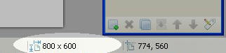
Create or open a file containing the sector borders of your map (SectorBorders.bmp) represented by black (RGB= 000000) lines. The size (pixel by pixel, displayed near the bottom right corner of the Paint.NET window) of SektorInfo.bmp should be exactly the same size as Map.bmpD.
Next, use the “Paint Bucket” tool (Shortcut: F) to fill each sector with a different color, starting with RGB= 000001, and continuing with 000002, 000003, etc. in consecutive order, by following these steps:-Step 1: Click on the “Paint Bucket” tool in the “Tools” window
-Step 2: Click on the “More >>” button in the “Colors” window
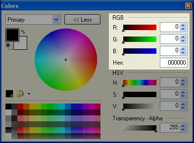
-Step 3: In the “RGB” section, set the R (Red) and G (Green) values to 0, and the B (Blue) value to 1.
-Step 4: Click on a sector with the fill tool to fill the sector with your selected color. All areas that contain the exact same RGB color value will be considered one sector, even if they are discontinuous.
-Step 5: Increase the B (Blue) value by 1 in the colors window and repeat steps 4 and 5 until all sectors have been filled. Filling sectors in some kind of patterned order (e.g. starting in the left hand corner and filling each sector in a row across the top, or filling all sectors belonging to one power before moving to another power) may make things easier later.
-Step 6: When you have finished, save your file as “SektorInfo.bmp” in your module’s .gim folder. Use 24-bit depth. I would not recommend playing with the dithering level, as it could crash the program.I have not tried it, but theoretically if you have more than 255 sectors, you would add 1 to the G (Green) value and reset the B (Blue) value to 0 for your 256th sector, and continue to add 1 to the B value for each subsequent sector. The program uses these RGB values to identify an area of the map with a line in SektorInfo.txtN/SektorInfo.sekL. The definition of the sector colored with RGB value 000001 will be the first line SektorInfo.txtN/SektorInfo.sekL, and so on. So, if you are adding sectors to an existing SektorInfo.bmp, please note that the RGB (“Hex”) hexadecimalQ value (which is equal to the B (Blue) value if you have fewer than 256 sectors and pseudo-sectors) must correspond to the line in SektorInfo.txtN/SektorInfo.sekL where the sector is defined.
-
Section F: SektorInfo.map
SektorInfo.map contains the information of which sector (territory, sea zone, space, etc.) each pixel on the map belongs to. It is not required, but if used, it does require the accompaniment of SektorInfo.sekL. Without these two files, a module will not contain any distinction of territories or sea zones, so IPC income calculations in the program’s “InfoView” window are not possible. It is created from SektorInfo.bmpE using b242map.exeP.
Creating SektorInfo.map
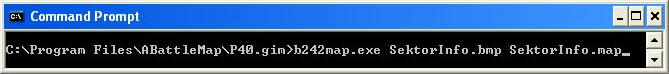
Refer to Section P for instructions on using b242map.exeP to create SektorInfo.map. The syntax is “b242map.exe SektorInfo.bmp SektorInfo.map”.
-
Section G: ToolPieces.bmp
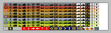
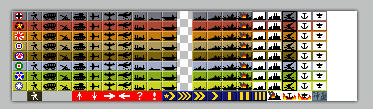
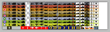
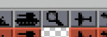
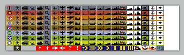
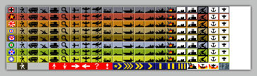
ToolPieces.bmp is the default image file displayed in ABattleMap’s “ToolBar” window when a user does not have the “Use BigPieces” option selected in ABattleMap’s “View” menu. This file is required.
Creating ToolPieces.bmp
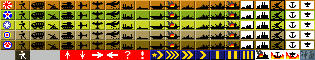
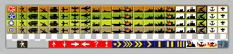
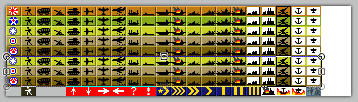
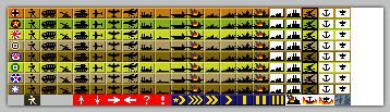
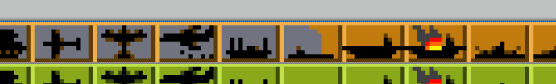
ToolPieces.bmp is created as a grid of pieces, and each piece must be exactly 15x10 pixels in size without gaps between them. Each row represents the pieces belonging to a specific power. Rows should be (but do not have to be) in the same order as game’s turn order. Each column represents pieces of a specific type. The first column is always considered the power’s flag or control marker. Subsequent columns can be in any order, as long as they are consistent with the order defined in ToolPieces.txtJ or UnitStats.txtI if one of those files exist. If your module requires miscellaneous pieces that do not belong to a specific power, you should include them in an additional row placed last, since including them in a row belonging to a specific power may affect that power’s “InfoView” statistics.In my opinion, the easiest way to create ToolPieces.bmp is to modify an existing ToolPieces.bmp from a different module (the alternative is to draw it from scratch). You may want to ask permission from the original creator of the file, but many good files seem to be a conglomeration of efforts.
-Step 1: Copy an existing ToolPieces.bmp file from another .gim folder into your own.
-Step 2: Open the file in Paint.NET
-Step 3: If the file you are modifying has more rows of toolpieces than you need, use the “Rectangle Select” tool to select the rows you do not need and delete them.
If you do not need to create new rows of toolpieces, you may skip to step 7.
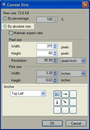
-Step 4: If needed, expand your canvas by clicking the “Image” menu > “Canvas Size…”, or by pressing Ctrl+Shift+R and increasing the height or width as necessary. You probably want your anchor to be “Top Left”
-Step 5: If the file you are copying from has a bottom row of miscellaneous pieces that you would like to keep, select it using the “Rectangle Select” tool and move it to the bottom of the canvas using the “Move Selected Pixels” tool.

-Step 6: Add the appropriate number of rows of pieces by copying one of the existing rows (“Rectangle Select”, Ctrl + C), and adding it beneath the existing bottom row (Ctrl + V, Ctrl + Arrow Keys) until you have the desired number of rows.
-Step 7: Replace the images in the first piece of each row to correspond with the powers involved in your module’s game. The power represented in the first row of pieces will be “Power 1”, and should (recommended) be the first power in your game’s turn order. Power 2 will be in the second row, and so on.
You will now use the “Recolor” tool to recolor the toolpieces. Usually, rows of toolpieces have three colors that distinguish them from other rows: a main color, a highlight, and a shade. The main color usually corresponds with the color used to fill that power’s originally-owning territories in Map.bmpD. The highlight is a lighter value of the main color, and the shade is a darker value. If you do not need to recolor your toolpieces, you may skip to step 15.
-Step 8: Use the “Rectangle Select” tool to select only the row of toolpieces that you wish to recolor.

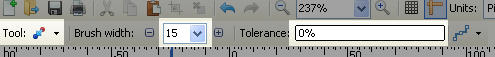
-Step 9: With the “Recolor” tool selected, set the “Tolerance” setting to 0% and the brush width to at least 15.
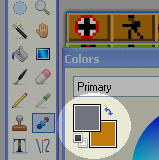
-Step 10: Set your primary color in the “colors” window to the main color you wish to use for the toolpieces row you have selected. If you have already created Map.bmpD, you can select your primary color by opening Map.bmpD, holding the Ctrl key (on your keyboard), and clicking on the color used to identify the power whose toolpieces you are recoloring. Set your secondary color to the color you wish to replace, by holding the Ctrl key and right-clicking the main color in the toolpieces row you have selected.
-Step 11: Use the recolor tool to paint over your entire selected area. All instances of your secondary color will be replaced by your primary color.
-Step 12: Select your primary color in the “Colors” window and increase its value in the “HSV” section of the expanded “Colors” window. Hold Ctrl and right-click the highlights in your selected toolpieces row to designate it as the color to be replaced. Recolor your selected row of toolpieces as you did in step 11.
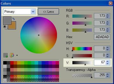
-Step 13: Repeat step 12, only this time decrease the value of your primary color and select the shadows as the color to be replaced. This should complete the recoloring of your row.
-Step 14: Select a new row to be recolored by using the “Rectangle Select” tool, or by using the “Move Selection” tool and pressing Ctrl + Down Arrow on your keyboard (this moves your selection down 10 pixels). Repeat steps 9 through 14 until all rows have been recolored appropriately.
-Step 15: If there are any columns of toolpieces you do not wish to use in your module, you can select and delete them.
-Step 16: Use the “Rectangle Select” and “Move Selected Pixels” tools to rearrange your toolpieces, so that you have 15-pixel-wide columns where you wish to add a new column of toolpieces, and all other rows and columns are aligned.
You will now create your new toolpieces. If you do not wish to create new toolpieces, you may skip to step 23.
-Step 17: Draw or copy a blank toolpiece into the space you wish to create a new toolpiece.
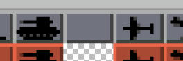
-Step 18: Use the “Pencil” tool to draw the image of the new toolpiece you wish to create.
-Step 19: Select the new toolpiece using “Rectangle Select”.
-Step 20: Copy the new toolpiece into other rows by pressing Ctrl + C, Ctrl + V, and Ctrl + Down Arrow. Repeat as necessary.
-Step 21: Repeat steps 17 through 20 until your toolpieces palette contains all the pieces you wish to use in your module.
-Step 22: Use the “Recolor” tool to recolor your new toolpieces to fit the color of their pertaining rows (refer to steps 8 through 14 for a general process of how to use the “Recolor” tool).
-Step 23: Once all your toolpieces are colored and arranged the way you want them, ensure that each row is exactly 10 pixels in height, and each column is exactly 15 pixels in width.
-Step 24: Finally, use “Rectangle Select” to select all and only your toolpieces palette. Check the bottom-left corner of the Paint.NET window to ensure that the width of your selection is exactly 15 pixels times the number of columns of toolpieces, and the height of your selection is exactly 10 times the number of rows of toolpieces.

-Step 25: Press Ctrl + Shift + X on your keyboard to crop your image to your selection.
-Step 26: Use the “File” menu > “Save As…” or press Ctrl + Shift + S to open the “Save As” window.
-Step 27: Navigate to your module’s .GIM folder to save your file in that location. Type “ToolPieces” in the “File Name:” field, and select “BMP (*.bmp)” in the “Save as type:” field.
-Step 28: Click the “Save” button, replacing any existing file if necessary (rename the existing file beforehand if you wish to keep it). Use 24-bit depth. I would not recommend playing with the dithering level, as it could crash the program. -
Section H: BigPieces.bmp
BigPieces.bmp is the image file displayed in ABattleMap’s “ToolBar” window when a user has the “Use BigPieces” option selected in ABattleMap’s “View” menu. It allows the user the option of a larger toolpieces palette. This file is not required: when a module does not contain a BigPieces.bmp file, the “ToolBar” window will always display Toolpieces.bmpG.
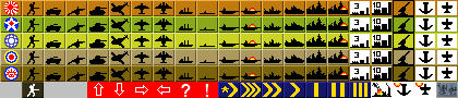
Creating BigPieces.bmp
Like ToolPieces.bmpG, BigPieces.bmp is created as a grid of pieces, but each piece must be 20x15 pixels in size without gaps between them. Each piece corresponds to the piece in the exact same relative location in Toolpieces.bmpG. In other words, the piece represented in column X and row Y of BigPieces.bmp must also be the piece represented in column X and row Y of ToolPieces.bmpG. As with Toolpieces.bmpG, I think the easiest way to create BigPieces.bmp is to modify an existing BigPieces.bmp. You may want to ask permission from the original creator of the file, but many good files seem to be a conglomeration of efforts. Following the steps in Section G for creating ToolPieces.bmpG should give you a good idea of how to create BigPieces.bmp, as long as you remember that each piece in BigPieces must be 20x15 pixels instead of 15x10 pixels. If you are changing pieces or creating new ones, be sure to use your ToolPieces.bmpG file as a reference, since corresponding pieces must be located in the same column and row locations in each image file. -
Section I: UnitStats.txt
UnitStats.txt is a newer version of “ToolPieces.txtJ” (new in version 0.80+), and contains the IPC cost/value, type (“Land”, “Naval”, “Air”, or “Build”), and convoy disruption (“Damage”) value of each column of units on the “ToolPieces” palette. It is not required, and its function will replace that of “Toolpieces.txtJ” if both files are present.
Creating UnitStats.txt
UnitStats.txt is constructed in the same way as ToolPieces.txtJ, except each line (piece) has three number values instead of 2. Refer to an existing UnitStats.txt or Toolpieces.txtJ file to see how it is constructed:
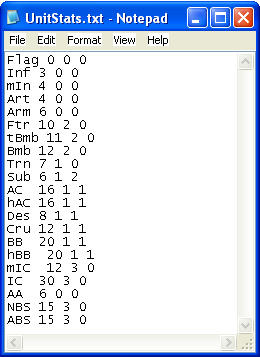
- Each line of the text file corresponds to each column, in sequential order, of toolpieces in ToolPieces.bmpG and BigPieces.bmpH.
- Each line begins with the name (or an abbreviated name) of the toolpiece to which it corresponds. This name is arbitrary. It is not used by the program [as far as I can tell]; it only helps you identify which piece each line belongs to.
- Each name is followed by three numbers, and each number is separated by a space:
o The first number is the piece’s IPC cost/value. This number is used to calculate a power’s assets in the program’s “InfoView” window.
o The second number identifies which type of unit is represented by the toolpiece. This determines which line of assets in the “InfoView” window includes the piece’s IPC value. 0 = “Land”, 1 = “Naval”, 2 = “Air”, 3 = “Build” (short for “Buildings”, or “Facilities”).
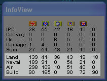
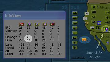
o The third number is the piece’s convoy disruption value. For example, in the “Pacific 1940 v3.1” module, subs are given a convoy disruption value of 2. Sectors can be designated as convoy zones in SektorInfo.txtN/SektorInfo.sekL, each with a list of sectors designated as susceptible to its convoy disruption (see “Section M: Using Sektor Editor”). When a sub is placed in one of these convoy zones, its convoy disruption value is subtracted from the income value of the susceptible sectors in the owning powers’ incomes. This is reflected in the “Damage” and “Sum” rows of the income section of the “InfoView” window. Note that this effect is contingent on “At War” status.
-
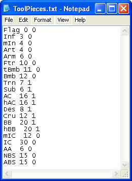
Section J: ToolPieces.txt
ToolPieces.txt is an older version of “UnitStats.txtI” and contains the IPC cost/value and type (“Land” or “Naval”) of each column of units on the “ToolPieces” palette. It is not required, and is not utilized if a UnitStats.txtI file exists in the module (unless the program is version 0.80 or earlier). Including both ToolPieces.txt and UnitStats.txtI in your module will provide compatibility for older ABattleMap versions.
-
Section K: MapInfo.txt
MapInfo.txt is a text file that contains the name of the module as it appears in ABattleMap’s “View” menu. It also includes the information of which powers are aligned together on a team. It is required.
Creating MapInfo.txt
Refer to an existing MapInfo.txt file to see how it is constructed:
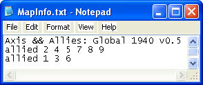
- The first line is the name of the module. It displays in ABattleMap’s “New” drop-down menu and is selected by the user to open the module. Notice that the “&” (ampersand) character must be preceded by another “&” character in order to be displayed within the ABattleMap menu.
- Subsequent lines identify listed powers as allied together. This information is used, for example, for convoy route or national objectives purposes, where a sector or group of sectors must be controlled by a power’s side for that power to receive an amount of income. These lines must begin with the word “allied”, followed by a list of single-digit integers representing powers. The line “allied 1 3 6” shows that powers 1, 3, and 6 are allied together. Powers are numbered by their order in ToolPieces.bmpG and BigPieces.bmpH. Note that powers numbered 10 or greater cannot be a part of these lists (as far as I can tell).
- The first line is the name of the module. It displays in ABattleMap’s “New” drop-down menu and is selected by the user to open the module. Notice that the “&” (ampersand) character must be preceded by another “&” character in order to be displayed within the ABattleMap menu.
-
Section L: SektorInfo.sek
SektorInfo.sek contains all the information (except map/board location) about specific sectors, including name (as displayed in ABattleMap’s title bar), type (land or water), IPC value, original owner, and much more. It also includes other special sector-related information, such as damage/“convoy disruption” criteria. It is not required, but if used, it does require the accompaniment of SektorInfo.mapF. Without these two files, a module will not contain any distinction of territories or sea zones, so IPC income calculations in the program’s “InfoView” window are not possible. It is created from SektorInfo.txtN using csek.exeP, but can also be edited using ABattleMap’s Sektor EditorM. An existing SektorInfo.sek can be used to create SektorInfo.txtN with rsek.exeP.
Creating SektorInfo.sek
Refer to section P for instructions on using csek.exeP to create SektorInfo.sek. The syntax is “csek.exe SektorInfo.txt SektorInfo.sek”.
-
Section M: Using Sektor Editor
Sektor Editor is a tool included in ABattleMap beginning with version 0.80 (this section discusses the use of Sektor Editor in ABattleMap version 0.80+). It is accessed from ABattleMap’s “File” menu.
Sektor Editor provides a quick and easy way to edit many aspects of SektorInfo.sekL without the need to edit and convert SektorInfo.txtN. It cannot edit sectors not represented by space on the map (with SektorInfo.mapF), it cannot create new sectors, and it cannot edit the position of a sector’s “IPC Values” display. It is not intended to edit pseudo-sectorsN (which should not be represented on the map).
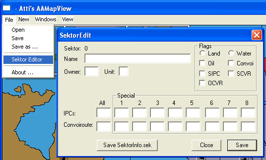
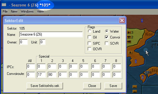
While the “SektorEdit” window is open, sector names in the main window’s title bar will be followed by the pertaining sector’s ID number between asterisks. This number corresponds to the sector’s line in SektorInfo.txtN/SektorInfo.sekL and RGB value in SektorInfo.bmpE/SektorInfo.mapF. Begin editing any sector on the map by clicking on it - each field in the “SektorEdit” window will be updated to reflect the current values of the sector.
Features of Sektor Editor
Buttons- “Save”: This button does not permanently institute changes and does not permanently affect SektorInfo.sekL, but applies all changes made to the current sector to memory and puts them into effect until you change modules (or reopen the same module) or close the program.
- “Save SektorInfo.sek”: This button will update your module’s SektorInfo.sekL file to reflect all changes that have been applied to memory using the “Save” button. Note that changes to made to any sector, including the current one, will not be reflected in SektorInfo.sekL unless they were first applied to memory using “Save”.
- “Close”: This closes the “SektorEdit” window. Any changes applied only to memory will remain until you change modules, reopen the module, or close the program.
Fields - “Name”: This text field is the name of the sector, displayed in ABattleMap’s title bar when the user hovers the cursor over the sector.
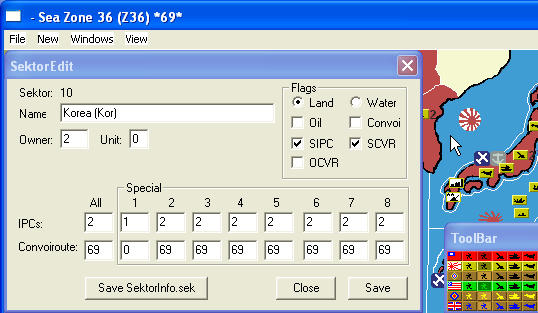
- “Owner”: This is the number of the power considered to be the original owner of the sector (powers’ numbers correspond to the sequence of the rows in ToolPieces.bmpG). The sector’s IPC value is included in the income of the original owner unless another power’s flag is placed on the sector.
- “Unit”: This field defines which unit the controlling power’s side must have on the sector in order for the controlling power to receive the sector’s IPC income. A value of 0 means no unit is required. A value of 1 means the unit in the second column of ToolPieces.bmpG (since the first column is only for flags) is required. 2 is the third column, and so on. Most modules do not use this feature.
- Flags - “Land” or “Water”: Distinguishes the sector as a land sector or a water sector. As far as I know, this distinction is obsolete in recent versions of ABattleMap.
- Flags - “Oil”: If checked, IPCs received by a power for controlling this sector are listed in that power’s “Oil” row of the “InfoView” window instead of the “IPC” row.
- Flags - “Convoi”: If checked, and “Flags - Oil” is unchecked, IPCs received by the original owner of this sector are listed in that power’s “Convoy” row of the “InfoView” window instead of the “IPC” row, and all other powers cannot receive income from this sector. If checked, and “Flags - SCVR” is unchecked, the “Convoiroute - Special (1-8)” fields can define sectors affected by convoy disruption occurring in this sector* (such as in “Seazone 19 (z19)” in the “Pacific 1940 v3.x” modules). Note that convoy disruption effects are subject to control of specific “at war” sectors (see “Pseudo-sectors” in section N).
- Flags - “SIPC”: Stands for “Special IPC”. If checked, values listed in the “IPCs - Special (1-8)” fields define the sector’s IPC income value according to which power controls it. For example, if “SIPC” is checked for sector 10, “IPCs - Special 1” is 5, and “IPCs - Special 2” is 3, then power 1 will receive 5 IPC for controlling sector 10, but power 2 will only receive 3 IPC for controlling the same sector. Note that there appears to have been an error in programming this, and “IPCs - Special 6” actually defines the value for power 8, “Special 7” is for power 6, and “Special 8” is for power 7. Most modules do not use this feature.
- Flags - “SCVR”: Stands for “Special Convoy Route”. If checked, values listed in the “Convoiroute - Special (1-8)” fields define what other sector each specific power must control in order to receive the IPC income value of the current sector. For example, if “SCVR” is checked for sector 20, “Convoiroute - Special 1” is 5, and “Convoiroute - Special 2” is 0, then power 1 must control both sectors 5 and 20 in order to receive the IPC income value of sector 20. Power 2, however, only needs to control sector 20 to receive its IPC income value as usual. Most modules do not use this feature.
- Flags - “OCVR”*: Stands for “Owner Convoy Route”. If checked, all convoy routes defined for the current sector must be controlled by the same power that controls the current sector in order for that power to receive the IPC income for the sector. If unchecked, all convoy routes defined for the current sector can be controlled by any power allied with the current sector’s controlling power in order for that controlling power to receive the IPC income for the sector. Most modules do not use this feature.
- IPCs - All: This field defines the IPC income value of the sector if the IPC value is the same for all powers.
- IPCs - Special (1-8): If “Flags - SIPC” is checked, these fields define the IPC income value of the sector according to which power (1-8) controls it. If “Flags - SIPC” is unchecked, these fields should all be 0. Note that these fields cannot hold values larger than 15. See the description of “Flags - SIPC” above for a more thorough explanation of special IPCs.
- Convoiroute - All: This field contains the ID number of another sector that must be controlled in order for a power to receive income from the current sector. If more than one other sector is required, the “Convoiroute - Special (1-8)” fields may be used** (beginning with “Special 1”) to define these additional sectors as long as “Flags - SCVR” is unchecked.
- Convoiroute - Special (1-8): If “Flags - SCVR” is checked, these fields define the sector (ID number) each individual controlling power (or controlling power’s side) must also control in order for the current sector’s IPC income to be received. See the description of “Flags - SCVR” above for a more thorough explanation of special convoy routes. Most modules do not use this feature. If “Flags - SCVR” is unchecked, these fields may be used** to define more convoy sectors for all powers in addition to the “Convoiroute - All” field. If “Flags - SCVR” is unchecked and “Flags - Convoi” is checked, these fields can define sectors affected by convoy disruption occurring in this sector* (such as in “Seazone 19 (z19)” in the “Pacific 1940 v3.x” modules). Note that convoy disruption effects are subject to control of specific “at war” sectors (see “Pseudo-sectors” in section N).
*This feature is new in ABattleMap version 0.80+
**This feature is new in ABattleMap version 0.80 -
Section N: SektorInfo.txt
SektorInfo.txt is the editable text file used with csek.exeP to create SektorInfo.sekL. Since SektorInfo.txt is not used by the program or module directly, an absence of it has no affect on the function of the module. Creating it is necessary only if you want to include sector information in your module with SektorInfo.sekL and SektorInfo.mapF files (by far the most technical part of creating a module).
Creating SektorInfo.txt
To create a blank SektorInfo.txt file, right-click any unused space in you .gim folder, select “New”, and select “Text Document”.

Rename your new text document “SektorInfo.txt”. From here, I recommend creating SektorInfo.sekL and using Sektor EditorM** to set all the available settings for each sector on the map.Editing SektorInfo.txt
Some sector information cannot be added to SektorInfo.sekL using Sektor EditorM. In these cases, the information must be included by editing a current copy of SektorInfo.txt and converting it back to SektorInfo.sekL. I will begin with what cannot be added using Sektor EditorM, and continue with a map of the rest of the information in SektorInfo.txt. Before editing SektorInfo.txt, you should always use rsek.exeP to create a current copy of SektorInfo.txt from SektorInfo.sekL so that SektorInfo.txt will reflect all changes made to SektorInfo.sekL using Sektor EditorM.The structure:
Each sector in your module is represented by one line in SektorInfo.txt. Each line has different parts, used for different pieces of information. The first part of each line is a character string which functions as the sector’s name that appears in ABattleMap’s title bar when a user hovers the cursor over the sector on the map. Following the sector name is a colon, which is then followed by nine sets of eight digits each. Each 8-digit set is called a long, and they are labeled “long1” through “long9” left to right. Each long may contain separate numbers, labeled according to the number of digits used: each set of two digits in a long is called a byte, labeled b1-b4 left to right, and each single digit I will call a nyble, labeled n1-n8 left to right.
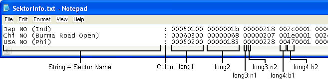
Note that all numbers in SektorInfo.txt must be written as hexadecimal valuesQ. Refer to section Q for an explanation of hexadecimal values.IPC Value display location:
Long2 and long3 in each line define the location of the sector’s IPC value display when a user selects “IPC Values” in ABattleMap’s “View” menu.
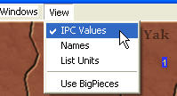
Long2 is the location’s X-value, or horizontal distance in pixels from the left side of the image. Long3 is the location’s Y-value, or vertical distance in pixels from the top of the image. To identify the X and Y values of a specific location on the map, open Map.bmpD in Paint.NET. Hover your cursor over a location where you would like the IPC value of your sector to be. The bottom-right corner of the Paint.NET window shows the X and Y values (respectively) of that location separated by a comma.
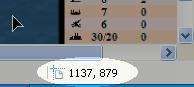
Convert each value from decimal to hexadecimalQ, and then type them into long2 and long3 of the pertaining sector. For example, if your “X, Y” value for sector 1 is “1137, 879”, then long2 of sector 1 should be “00000471”, and long3 should be “0000036f”.Pseudo-sectors*:
SektorInfo.txt/SektorInfo.sekL can include some information that does not pertain to a specific sector. This information is not represented by space on the map, but does exist in a line of SektorInfo.txt as a pseudo-sector. Pseudo-sector lines are structured in the same way as all sectors with a string (name), colon, and 9 longs, but each long in a pseudo-sector contains different information than the corresponding longs in normal sectors.One type of pseudo-sector (the only one I know of) is used for defining at-war status criteria (used for convoy disruption). In this pseudo-sector, long1 is “00000080”. Long2:b4 is the number of the aggressing power. Long2:b3 is the number of the sector which must be controlled by any power for the aggressing power to be considered “at war” with (afflict convoy damage against) power 1. Long2:b2 is the number of the sector which must be controlled by any power for the aggressing power to be considered “at war” with (afflict convoy damage against) power 2. Long2:b1 is the same for power 3, long3:b4 is for power 4, long3:b3 for power 5, and so on. For example, in the “Pacific 1940 v3.1” module, someone must control sector 192 (or C0 in hexadecimal) for Japan (power 1) to do convoy disruption damage to UK (power 4) or ANZAC (power 5), and someone must control sector 161 (or A1 in hexadecimal) for Japan to do convoy disruption damage to the US (power 2). Japan cannot do convoy disruption damage to China (power 3). In the module’s SektorInfo.txt, this is shown with the following line:
atWarStatus Japan: 00000080 00a10001 0000c0c0 00000000 00000000 00000000 00000000 00000000 00000000The Rest:
The following is a map of what each location (in order) of each line in SektorInfo.txt defines (for normal sectors). Named features are references to fields in Sektor EditorM:- String- This is the name of the sector. Any white space between the last visible character of the string and the colon is ignored.
- Colon- This separates the string from the numerical codes
- Long1:b1- “01” is for land, “00” is for water
- Long1:b2- IPC value of sector
- Long1:b3- original owner of sector
- Long1:b4- defines type of pseudo-sector*; always “00” for normal sectors
- Long2- X-value of IPC value display location
- Long3- Y-value of IPC value display location
- Long4:b1- always “00” (as far as I can tell)
- Long4:b2- corresponds to “Convoiroute - All”
- Long4:n5- always “0” (as far as I can tell)
- Long4:n6- corresponds to “Flags - Convoi” (“1” is checked, “0” is not)
- Long4:n7- always “0” (as far as I can tell)
- Long4:n8- corresponds to “Flags - Oil”, “Flags - SIPC”, “Flags - SCVR”, and “Flags - OCVR”*. Value for “Oil” is 1, “SIPC” is 2, “SCVR” is 4, and “OCVR” is 8. If more than one of these are applicable, add their values together.
- Long5:b1- corresponds to “Convoiroute - Special 4”
- Long5:b2- corresponds to “Convoiroute - Special 3”
- Long5:b3- corresponds to “Convoiroute - Special 2”
- Long5:b4- corresponds to “Convoiroute - Special 1”
- Long6:b1- corresponds to “Convoiroute - Special 8”
- Long6:b2- corresponds to “Convoiroute - Special 7”
- Long6:b3- corresponds to “Convoiroute - Special 6”
- Long6:b4- corresponds to “Convoiroute - Special 5”
- Long7:n1- corresponds to “IPCs - Special 6” (for power 8)
- Long7:n2- corresponds to “IPCs - Special 8” (for power 7)
- Long7:n3- corresponds to “IPCs - Special 7” (for power 6)
- Long7:n4- corresponds to “IPCs - Special 5”
- Long7:n5- corresponds to “IPCs - Special 4”
- Long7:n6- corresponds to “IPCs - Special 3”
- Long7:n7- corresponds to “IPCs - Special 2”
- Long7:n8- corresponds to “IPCs - Special 1”
- Long8:b1- always “00”
- Long8:b2- always “00”
- Long8:b3- always “00”
- Long8:b4- correspond to “Unit”
- Long9- always “00000000”
*This feature is new in ABattleMap version 0.80+
**This feature is new in ABattleMap version 0.80 -
Section O: Start.aam
Start.aam is the save file that contains the starting setup of pieces. This file is not necessary if there is no standard starting setup for your game. Note that the file contains the name of the module directory (.gim folder) that was used to create it, so it cannot be used for a module with a differently-named directory.
Creating Start.aam
Once you have created all the other desired files for your module, open your module in ABattleMap. Use your ToolBar to place pieces according to the way all games should begin in your module. I recommend using BigPieces (if you have them) for this so that you can adequately space the pieces for users who prefer to use BigPieces. Once you have finished, open the “File” menu, select “Save As…”, navigate to your module"s .GIM folder, type “Start” in the “File name:” field, and select “AAA Map (*.AAM)” in the “Save as type:” field. Press the “Save” button. -
Section P: Using ABattleMap’s file conversion tools
There are several application tools included in an installation of ABattleMap 0.79f which are helpful and/or required for creating certain files used in a module. The tools are:
b242map.exe - this is used for creating SektorInfo.mapF from SektorInfo.bmpE
csek.exe - this is used for creating SektorInfo.sekL from SektorInfo.txtN
rsek.exe - this is used for creating SektorInfo.txtN from SektorInfo.sekLYou may also notice a bmp2map.exe file in your ABattleMap folder, but I have no idea what this is for or how to use it.
Each of these files must exist in the same folder as the source file they use and the file they will create, so it is a good idea to make a copy of each of these files in your module’s .GIM folder while you are working on it. To do this, simply open your ABattleMap program directory in Windows Explorer (usually located at C:\Program Files\ABattleMap) and drag each one from your ABattleMap folder to your module’s .GIM folder while holding the “Ctrl” key on your keyboard.
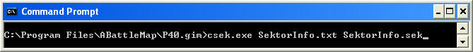
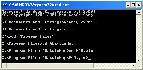
After you have the tool files in your module’s directory, you need to access them from the command console in order to use them. To open the command console, click “Start” and “Run…”. Type “cmd” in the “Run” window and press enter or click “OK”. You should see a black window with a file location followed by a blinking text insertion point, like this: “C:\Document and Settings\Stoney229>_”. This line is like viewing the “Stoney229” folder in Windows Explorer. To open a file in the “Stoney229” folder, you would type the file name and press enter. To open a subfolder in the “Stoney229” folder you would type “cd” (without quotes) followed by a space and the folder name and press enter. File or folder names that have at least one space require quotation marks (e.g. cd “My Documents” (with quotes)). To go up one folder you would type “cd…” (without quotes) and press enter.
You need to navigate from here to your module’s directory, so typing “cd…” and pressing enter will get you to C:\Document and Settings. “Cd…” and enter again will get you to C:. Once you are at C:, type “cd “Program Files”” (quotes around “Program Files” only) and press enter. Now type “cd ABattleMap” and press enter. Finally, type “cd” followed by a space and the name of your module’s directory (e.g. “P40.gim”) and press enter. Now you should be inside the folder containing all the files you need to access.
(Tip: instead of typing out the full name of a file or folder, you can type the first letter of the file or folder and press Tab on your keyboard to cycle through all files or folders beginning with that letter.)
From here you can use any of the .exe tools you have placed in your directory. To use b242map.exe to create a new SektorInfo.mapF file out of an existing SektorInfo.bmpE file, type “b242map.exe SektorInfo.bmp SektorInfo.map” (no quotes). SektorInfo.bmpE will remain in your folder and a new SektorInfo.mapF will appear.
To use csek.exe to create a new SektorInfo.sekL file out of an existing SektorInfo.txtN file, type “csek.exe SektorInfo.txt SektorInfo.sek” (no quotes). SektorInfo.txtN will remain in your folder and a new SektorInfo.sekL will appear.
To use rsek.exe to create a new SektorInfo.txtN file out of an existing SektorInfo.sekL file, type “rsek.exe SektorInfo.sek > SektorInfo.txt” (no quotes). SektorInfo.sekL will remain in your folder and a new SektorInfo.txtN will appear. Note that the required “>” between the source and destination files is unique to this tool.
-
Section Q: The hexadecimal number system
Using Windows Calculator to convert a number to hexadecimal
Open Windows Calculator by clicking Start>All Programs>Accessories>Calculator. Click the “View” menu and select “Scientific”. Type in a number to be converted to hexadecimal. Press F5 on your keyboard and the decimal number will be converted to hexadecimal. Press F6 to convert it back to decimal.Understanding the hexadecimal number system
Numbers are abstract entities which can be represented in a variety of different ways. Most of us represent numbers using a decimal (base-10) number system - that is, one with 10 different symbols, or digits, to represent all numbers. Our first 10 numbers: 0, 1, 2, 3, 4, 5, 6, 7, 8, and 9 only require one digit to be represented, but since there are only ten different digits, our eleventh number (10) requires a combination of digits, or symbols, to be represented. The way we do this is by assigning place values - we have a “ones” (100) place, the right-most digit of any number, and “tens” (101) place to the left of that, a “hundreds” (102) place to the left of that, and so on. When we’re used to using the decimal number system, we don’t have to think about the fact that the number 1265, for example, represents a number far larger then the measly number of 4 small digits it takes to represent the abstract 1265. Instead, we intuitively know that the “1” is really 1 thousand (103), the “2” is 2 hundreds (102), the “6” is 6 tens (101), and the 5 is 5 ones (100). In other words, as we count, when we run out of digits (7… 8… 9… ?), we add one into the next place and start over (10… 11… 12…). Using this method, we could create a number system using any number of digits and still be able to represent any number imaginable. Even if we only had 2 digits to work with, we could count: 0… 1… 10… 11… 100… 101… 110… 111… 1000… 1001… 1010… 1011… 1100… 1101… 1110… 1111… and so on. Using a smaller number of different digits requires more of the same digits to be used to represent a single number. The converse, however, is that if we used a number system based on something larger than ten, we would have more digits to work with and each number would be represented with a more efficient use of digits.The hexadecimal number system has 16 different digits: 0, 1, 2, 3, 4, 5, 6, 7, 8, 9, A, B, C, D, E, and F, in that order. What comes after F? 10 of course! Although F (hexadecimal) is the same number as 15 (decimal), the hexadecimal system has place values in the same way as the decimal system. There’s the ones (160) place, the sixteens (161) place, the two hundred fifty-sixes (162) place, and so on. So why does 10 (hexadecimal) represent the same number as 16 (decimal)? Because you have 1 sixteen and 0 ones, just like having 1 ten and 6 ones.
What’s 1265 (just a random number) in hexadecimal? The first thing to think about is how many places will it take? Does 1265 fit in the ones place of the hexadecimal number system? Are there 16 or more ones in 1265? Yes, so since we only have 16 different digits to put in each place, it must take more than one place. So then let’s look at the sixteens place: are there 16 or more sixteens in 1265? What is 16 16s? It is 256, so yes, there are more, and thus 1265 must take more than 2 places even in hexadecimal. So let’s look at the next place - are there 16 or more 256s in 1265? 16x256 is 4096, so no there are not 16 256s in 1265. That means the number 1265 (decimal) in hexadecimal must only take the ones place, the 16s place, and the 256s place - three places/digits in total. How many whole 256s are there in 1265? 1265/256=4.94140625, so there are 4 whole 256s in 1265. But 4 256s only accounts for 1024, and our number is 1265, so the remaining 241 must be represented in smaller denominations than the 256s. So the next place is the 16s place - how many whole 16s are there in 241? 241/16=15.0625. But how do we represent 15 in a single digit? In hexadecimal the 16th digit is F, so we have 4 256s, and we have “F” 16s. Those 15 (or “F”) 16s only account for 240 of our remaining 241, so we still have 1 left. We must move on to the ones place - how many whole ones go into 1? Exactly one! So since 1 thousand, 2 hundreds, 6 tens, and 5 ones are the same as 4 256s, 15 16s, and 1 one, then 1265 (decimal) must be the same as 4F1 (hexadecimal)!
Another way to think about it is this: Imagine going to a bank that only has dollar bills in denominations of 160 (1), 161 (16), 162 (256), 163 (4096) and so on. They will always give you change in the highest denominations possible, so that they handle the fewest number of bills. If you withdraw $1265, what bills will you get? You will get 4 $256-bills, 15 $16-bills, and 1 $1-bill.
That’s how it works!
-
Section R: .zip files
.ZIP files are like windows folders in that they can contain any number of files, but they package all the information up into one tidy file. Furthermore, they store redundant information in the files more efficiently so they take up less space on a computer or server and less bandwidth when being transferred over a network connection. These features make .zip files very useful for distributing the multiple files of an ABattleMap module over the internetS. Once files have been packaged into a .zip file, they can be easily extracted again for regular use using the Windows Extraction Wizard.
Creating a .zip file
To copy your module into a single .zip file, first create an empty .zip file by right-clicking an empty space in your ABattleMap program folder, selecting “New”, and selecting “Compressed (zipped) Folder”. Then drag your module’s .GIM folder onto the icon of the new .zip folder. If you have some extra files in your module’s directory, you may want to drag the necessary files of your module into the .zip folder one at a time. Now you have a .zip file containing your module, ready to upload to the internetS!Extracting a .zip file
To restore the contents of a .zip file, right-click the file, select “Extract All…”, and follow the instructions in the Extraction Wizard.
Suggested Topics